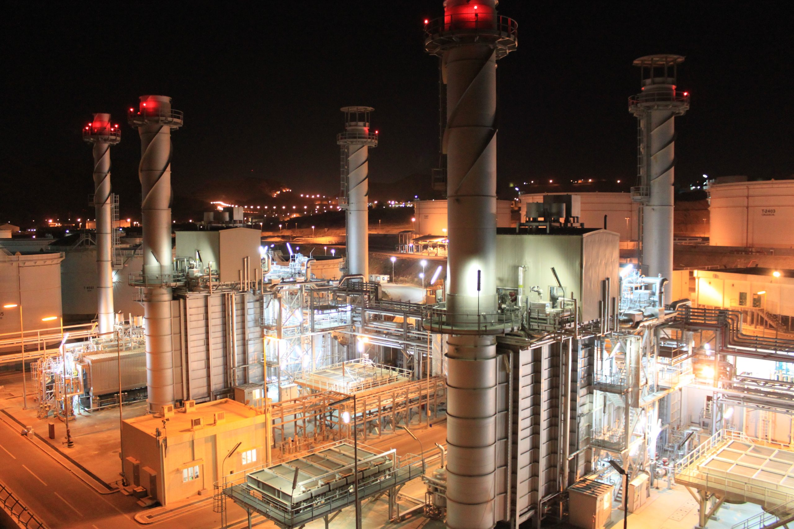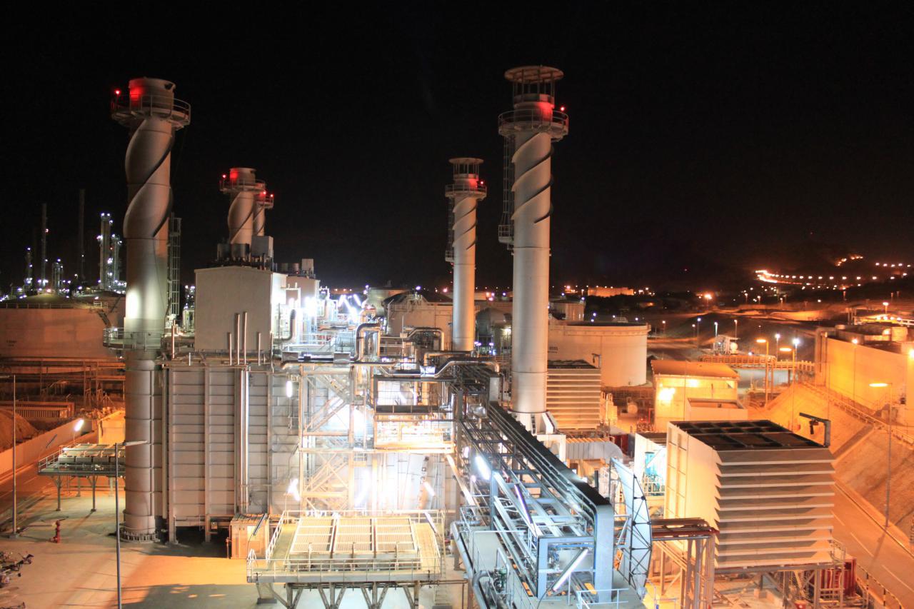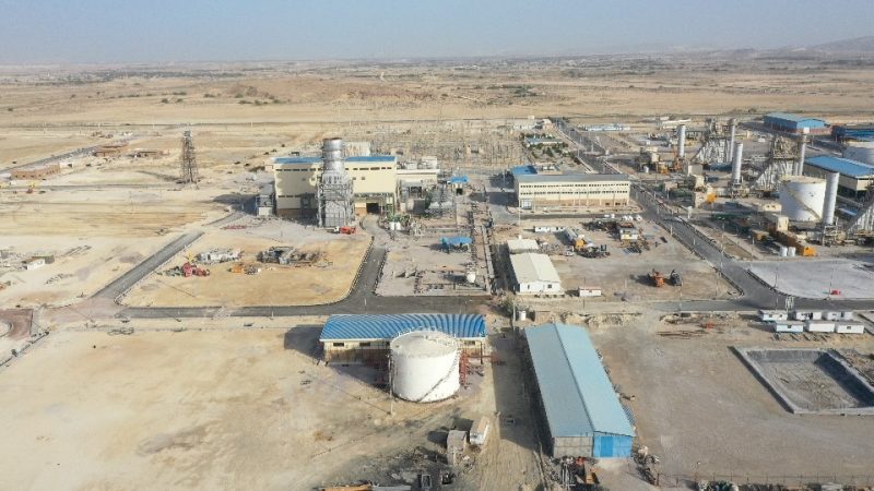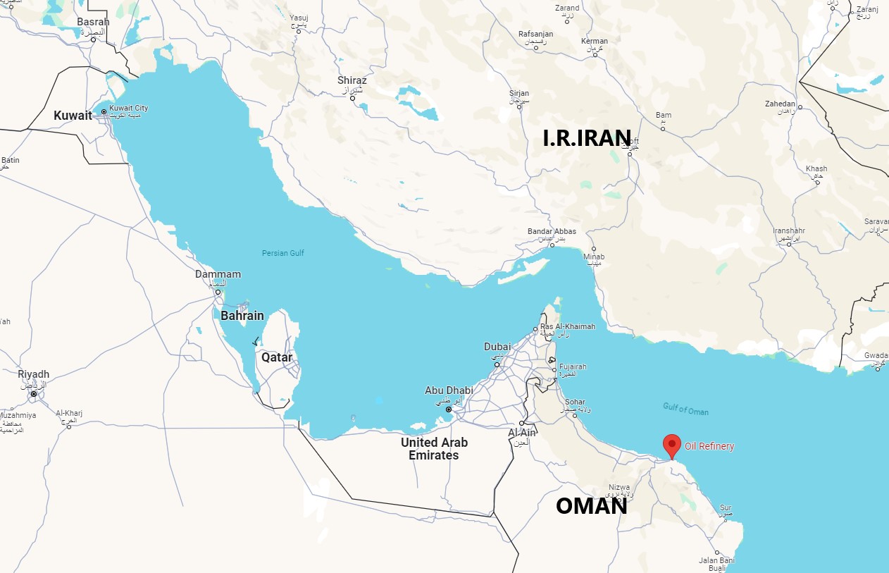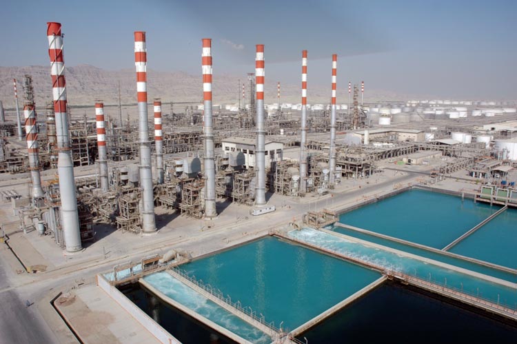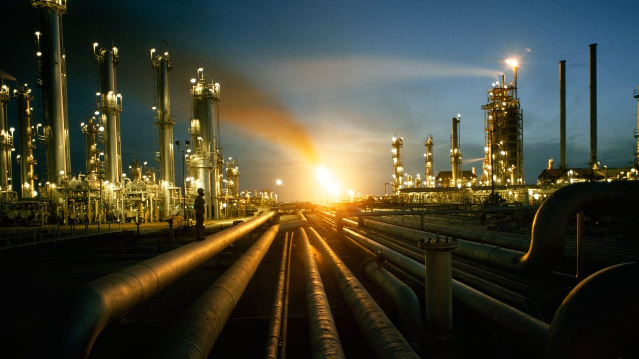
Cogeneration of electricity and water for Oman Oil Refinery including GTG, Aux. Boiler, HRSG and water polishing and desalination plants. A team of Iranian engineering, procurement and construction experts finished 54MW cogeneration plant and utility at its Mina Fahal refinery successfully. The contract is part of a plan to increase the refinery’s output to 105,000 barrels a day (b/d) from 85,000 (b/d).
ORPC has awarded this projects to Hirbodan among many well-known international competitors.
Scope of Services
- 2×25 MW Gas Turbine Power Generators (GE Frame 5)
- 2×100 TPH, Heat Recovery Steam Generator (HRSG)
- 1×30 TPH, Auxiliary Boiler
- Desalination Plant
- Polishing Plant
- Fuel Gas Conditioning
- DCS, FCS & SCADA Control System
Description
GAS TURBINE GENERATORS
Two (2) Gas Turbine model PG 5371 PA, each complete with auxiliaries and all other standard accessories with a nominal ISO rating between 24 to 28 MW are provided.
STEAM SYSTEM
The steam system consists of the following components:
MP steam header
The necessary steam requirement is met by steam produced in HRSGs, Auxiliary Boiler and the existing platformer boiler.
The Operating Pressure and temperature for MP Steam Header are as follows:
Pressure = 25 bar (g)
Temperature =350 0C
SHLP steam header
SHLP steam at Cogeneration area is derived from outlet of the FD fan drive turbines and connected to common cogen. SHLP header.
The Operating Pressure and temperature for SHLP Steam Header are as follows:
Pressure = 4.5 bar (g)
Temperature =296 0C
LP steam header
LP Steam is derived through desuperheating of SHLP steam. One desuperheating station is provided, which takes water from BFW discharge header for generating LP steam.
The Operating Pressure and temperature for LP Steam Header are as follows.
Pressure = 4.5 bar (g)
Temperature =200 0C
Two No. HRSGs
The HRSGs are designed for 2600 TPD of steam each.
In “exhaust gas mode” the flue gas coming from the GT is fed to the steam generator, which is designed as horizontal gas path, one (1) pressure level, natural circulation, top supported type.
The system is designed to receive feed water at the specified inlet conditions and to provide superheated steam at the supply conditions.
The steam/water mixture is separated in the HP steam drum and the dry saturated steam leaves the steam drum through steam take-off piping positioned along the top of the drum and flows through the super heater sections
One No. Auxiliary Boiler
Auxiliary boiler is foreseen for 720 TPD.
The Auxiliary boiler is foreseen for steam production for balance the steam produced by major equipment in various running case and in emergency load.
The combustion chamber of the Auxiliary boiler is equipped with dual fuel burners (gas or fuel oil burner); FD fan is provided for combustion air demand.
WATER DESALINATION PLANT
Desalination Plant for Oman Refinery Cogeneration Power Plant is based on the Multi-Effect Distillation with Thermal Vapour Compression ( MED-TVC) technology.
The principle of Multiple Effect Distillation consists in the recovery of the latent heat released by condensation of the vapour produced in each effect for the evaporation of the antifoam in the following effect.
The process of the vapour condensation- antifoam evaporation is repeated in each effect, at decreasing temperature and pressure. Finally, in the last effect part of the vapour produced is extracted from the thermo compressor, mixed with motive steam and discharged to the first effect. The remaining part of vapour produced in the second effect is led to an external distillate condenser. the whole distillate stream is collected in this condenser, then extracted with a pump and delivered to storage.
FUEL GAS SYSTEM
Natural gas for Cogeneration power plant will be supplied through a gas metering station at 21 bar (g) and 50C. The natural gas required for process and HRSG & Aux Boiler and also for gas turbines is heated by the separate heat exchangers to 400C.
Natural gas is led to GT skid through filter separator and coalescer filter.
One electric heater would be provided for heating of natural gas during initial starting of gas turbine.
GT FUEL OIL SYSTEM
The fuel oil firing in Gas Turbine would be carried out during the non-availability of natural gas.
The Gas Turbine Fuel oil system consists of following equipment:
- Fuel oil transfer Pumps
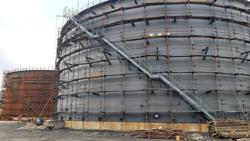
- Daily fuel oil storage tank
- Fuel oil forwarding pumps
HRSG FUEL OIL SYSTEM
Fuel oil firing in HRSGs and auxiliary boiler would be carried out during non-availability of natural gas. The fuel oil for the power plant is tapped off from the existing fuel oil supply network and supplied to HRSGs 1 & 2 and auxiliary boiler individually.
FLARES, VENTS & N2 PURGING SYSTEM
The purpose of the system is to collect the drains, vents and relief valve outlets from the equipments such as fuel gas mixing vessel, fuel gas heat exchangers and fuel gas piping.
The governing case for sizing the flare header is the operation of relief valves on the mixing vessel when both gas turbines are running and one HRSG is generating steam at MCR case.
Nitrogen purging provision has been envisaged to purge the fuel gas system before any maintenance activities. Nitrogen connection would be provided in all dead ends of flare header in addition to the normal fuel gas connection for purging.
COMPRESSED AIR SYSTEM
The compressed / instrument air required for plant is provided by taking tap off from the existing instrument air header The instrument air will be led to various consumers through an instrument air receiver of capacity 5 cu.m.
1 x 100% air compressor of 25 cu.m/hr and 1 x 100% air dryer to cater to the black start instrument air requirement is considered for Cogeneration area. The supply pressure for Instrument air is 7 bar (g).
POTABLE WATER SYSTEM
Potable water is tapped off from the existing treated water supply network. The flow to cogen area is around 10 m3/hr.
POTABLE WATER SYSTEM
The cooling water system consists of the following components:
- Cooling water pumps – 2 x 100 %
- Cooling Water Expansion Vessel
- Chemical Pot Feeder Vessel
- Fin Fan Cooler
The purpose of the Cooling water system is to supply the required quantity of Cooing water to GTGs (flame scanner cooling and atomizing air pre cooler), HRSGs, Auxiliary boiler and SWAS system.